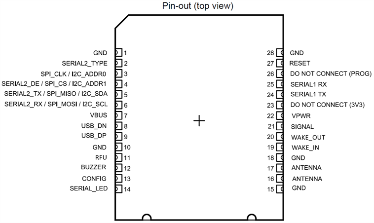
VTAP25 Pin description
|
Pin no. |
Pin name |
Type |
Description |
|
1 |
GND |
Power supply |
|
|
2 |
SERIAL2_TYPE |
Input |
Input I2C or SPI selection. Pull low for SPI, high for I2C |
|
3 |
SPI_CLK / I2C_ADDR0 |
Input |
Configurable: |
|
4 |
SERIAL2_DE / SPI_CS / I2C_ADDR1 |
Input |
Configurable: |
|
5 |
SERIAL2_TX / SPI_MISO / I2C_SDA |
Input/Output |
Configurable:
|
|
6 |
SERIAL2_RX / SPI_MOSI / I2C_SCL |
Input/Output |
Configurable: |
|
7 |
VBUS |
Power |
USB 5V - note this does not power the module, only for data enable |
|
8 |
USB_DN |
Input/Output |
USB data |
|
9 |
USB_DP |
Input/Output |
USB data |
|
10 |
GND |
Power supply |
|
|
11 |
RFU |
Input/Output |
Reserved for future use. Recommend connecting this pin to host GPIO, so that its functionality can be used when supporting firmware is released. |
|
12 |
BUZZER |
Output |
3V3 logic drive for external buzzer - variable frequency, 50/50 mark/space |
|
13 |
CONFIG |
Input |
Pull low to bypass config.txt on startup |
|
14 |
SERIAL_LED |
Output |
Serial LED 3V3 logic output - ‘Neopixel’ protocol. Host must provide 5V driver |
|
15 |
GND |
Power supply |
|
|
16 |
ANTENNA |
Input/Output |
Connect to antenna via matching circuit |
|
17 |
ANTENNA |
Input/Output |
Connect to antenna via matching circuit |
|
18 |
GND |
Power supply |
|
|
19 |
WAKE_IN |
Input |
Driven by the host processor to wake VTAP25 from deep sleep mode. Details with next firmware release NOTE: In firmware before v2.4.0.0 this pin had the opposite sense. If you have a design using pin 19 as a WAKE output, this can be accommodated with a custom VTAP25 configuration option, please contact vtap-support@dotorigin.com for details. |
|
20 |
WAKE_OUT |
Output |
Driven high by VTAP25 when a tap payload or other event is available to be read. Can also be used to wake up the host processor. |
|
21 |
SIGNAL |
Output |
Flag signal for data availability on the host connected serial interface (I2C/SPI) |
|
22 |
VPWR |
Power supply |
Power to module. 3.3V to 5V |
|
23 |
DO NOT CONNECT (3V3) |
- |
|
|
24 |
SERIAL1_TX |
Output |
Serial comms transmit |
|
25 |
SERIAL1_RX |
Input |
Serial comms receive |
|
26 |
DO NOT CONNECT (PROG) |
- |
|
|
27 |
RESET |
Input |
Pull low to reset module |
|
28 |
GND |
Power supply |
|
The VTAP25‑MOD reader module has no antenna. Before you can use any VTAP reader functionality, it requires connection of an external antenna, with a suitable matching circuit.
