VTAP25 Peripherals
Serial interfaces
The VTAP25 reader module offers synchronous and asynchronous communications over two serial comm ports.
SERIAL1
SERIAL1 allows asynchronous comms at 3V3 logic levels.
SERIAL2
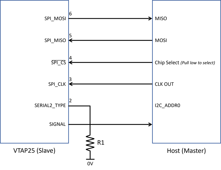
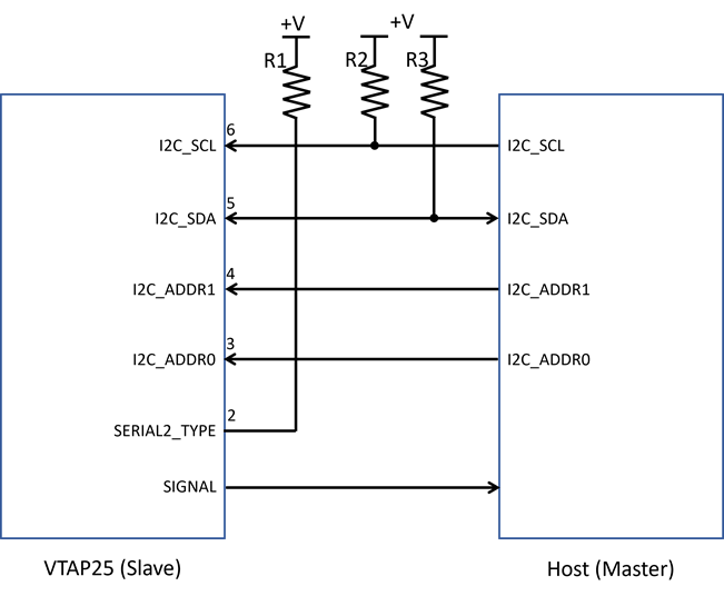
SERIAL2 may be configured for asynchronous comms, SPI or I2C – all at 3V3 logic levels. By default, SERIAL2 will use synchronous communication (SPI or I2C) unless set asynchronous (UART) communications are configured explicitly in config.txt.
Use the module pin SERIAL2_TYPE (Pin 2) to choose between SPI and I2C. Pull low for SPI, and pull high for I2C. The host board should connect the SERIAL2_TYPE pin appropriately to select the required communication interface.
Asynchronous comms (3V UART) are enabled using the config.txt.
Optionally, an RS‑485 transceiver can be connected to SERIAL2_TX, SERIAL2_RX and SERIAL2_DE (for transmit enable).
See the other VTAP guides and application notes for more information about configuration methods, communication protocols, settings and commands.
Note: It is recommended that you have a USB data connection (just 4 pins or test pads) provided on the host board to allow for firmware or config update/initialisation, in case communication with the host is not available via the preferred interface. For temporary use only, this can be just a direct connection to VBUS, D+, D- and GND (without USB inductors or suppression) for example via an unpopulated 4 way PCB header.
USB
The USB interface is USB2.0. The VTAP25 appears as a removable drive, virtual ComPort (VCP) and Human Interface Device (HID) on USB. The config.txt file referred to elsewhere is stored on the removable drive. The VCP and HID modes can be configured using the config file.
USB interface is implemented even if it is not required for user function. This will allow access to the module for easy configuration / firmware upgrade if the preferred interface is not available.
If USB mass storage drive is required, ensure the LOCK pin is not pulled low as this will disable the mass storage.
Recommendations for USB
USB layout rules should be followed. A filter and protection circuit is recommended ‑ see NFC USB reader example for a reference circuit.
If connection is via USB‑C, fit 5K1 resistor A5 to 0V and 5K1 resistor from B5 to 0V so that the host device can detect connectivity and power identification.
Serial LEDs
The device has serial LED output (Neopixel) for connecting a chain of up to 255 external serial LEDs. These can be configured to show a default colour permanently, and then automatically change colour (or flash) in response to a successful pass read, successful card read or error conditions. Custom LED sequences are also possible in response to successful reads.
The output is 3V3 logic and the host must provide 5V translation, as required. The VTAP25 does not provide power for the LEDs. See the example schematics for an external LED circuit diagram.
Refer to the other VTAP guides and application notes for more information on how to configure the serial LED output.
Buzzer
There is also a buzzer output for an external AC buzzer, which can be configured to beep on start-up, or in response to a successful pass or card read. The output is 3V3 logic drive (50/50 square wave) – user must provide the buzzer driver circuit. See the example schematics for an external buzzer circuit diagram.
Refer to other VTAP guides and application notes on how to configure the buzzer output.
Config bypass on startup
In a scenario where config.txt needs to be bypassed on startup, for example if SERIAL2 interface is erroneously changed to UART, where the physically connected interface is SPI or I2C, you can pull the CONFIG pin (13) low to bypass the configuration on startup. This way the physically connected interface can be connected to the VTAP25 and config.txt can be updated.
Signal
The signal output is used as a flag signal for when data is available to be transmitted on the Serial 2 interface (SPI or I2C). This allows the host to avoid continuous polling for data.


