Connect an RS‑232 serial scanner
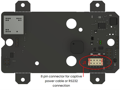
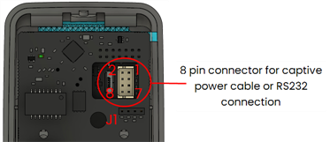
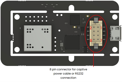
Barcode scanners or QR scanners with an RS‑232 output can be connected to VTAP100 and VTAP50 readers on the J1 header. J1 is a 2mm 8‑way captive cable connector for power, USB and RS‑232, which is present on all VTAP100 and VTAP50 readers.
Wiring RS‑232 serial scanner input
The position of the J1 connector in current hardware is illustrated below. More details can be found in the installation or integration guide for your VTAP reader model.
Note: If the J1 connector is already used by a captive USB cable, then that cable will need to be replaced with a custom cable that can connect both USB and RS‑232 at the same time.
A scanner will use pins 1,5,7 on a matching connector (Hirose DF11‑8DS‑2C or equivalent). If the VTAP reader power source, typically USB, can support the additional current requirement of your chosen scanner, then 5V on pin 3 could also be used to power the barcode or QR scanner.
This table shows the pin‑to‑pin connection between the J1 connector on your VTAP reader and your RS‑232 barcode or QR scanner:
|
VTAP100/VTAP50 J1 connector |
RS‑232 barcode or QR scanner |
|
|
Pin 1 |
0V |
0V |
|
Pin 3 |
+5V |
+5V |
|
Pin 5 |
RS232‑RX |
RS232‑TX |
|
Pin 7 |
RS232‑TX |
RS232‑RX |
Note: Always ensure that 0V is connected between the VTAP reader and the barcode/QR scanner. The 5V pin 3 connection is only required if powering the scanner from the VTAP reader.
General configuration to use serial scanner
In most cases the output interface for scanner data will be the same one already in use for other VTAP tap data.
If you have a VTAP PRO reader in Cloud mode, its configuration will be set up and sent through VTAP Cloud. Contact vtap‑support@dotorigin.com for help or more information.
For VTAP readers in Local mode, you should ensure that the following settings are in the config.txt file on your VTAP reader:
-
SerialScannerMode=1 to identify that a scanner input is connected on the RS‑232 interface.
-
If the ...Source setting for the output interface is set to any value other than =A5 (default), add 0x04 to the existing source bit value, to permit scanner data to be sent over that interface. (If the setting is not present in the config.txt file, the default value will allow scanner data through).
-
If required, you could define a delimiter value to identify the end of a scanner payload using the SerialScannerDelimiter setting. The default is =%0d (carriage return).
-
You might need to update the SerialSettings, to ensure that they match the serial settings of the barcode/QR scanner. The default is =9600,n,8,1 where 9600 is baud rate, n is no parity, 8 data bits, 1 stop bit.
Other settings for this output port can be adjusted to suit your application. Refer to the VTAP Commands Reference Guide for a complete set of available configuration settings.
The VTAP reader interface you choose to output scanner data may require some extra configuration, described in the following examples. Choose any of the following, if they are available on your VTAP reader model:
Check whether either of these settings are already included in the config.txt file on your VTAP reader and, if so, that their values permit this new use of the virtual COM interface:
-
If a ComPortMode setting is already included, ensure it reads ComPortMode=1, or delete the setting, to enable the virtual COM port. (The setting can simply be omitted because the virtual COM port is enabled by default, if not defined in the config.txt file).
-
If a ComPortSource setting is already included, and is set to any value other than =A5 (default), add 0x04 to the existing source bit value, to permit scanner data to be sent over the virtual COM interface. (Again, if this setting is not present in the config.txt file, the default value will allow scanner data through).
!VTAPconfig

SerialScannerMode=1        ; Enable reading scanner input on Serial RS-232
SerialScannerDelimiter=%0a ; Treat new line as end of scanner input
ComPortSource=85           ; Add 0x04 (scanner) to 0x81 (passes and
                           ; cards/tags) assuming default A5 is
                           ; unsuitable for some reason
ComPortPostfix= %09Type:$t ; Include type of read data
                           ; (wallet pass, cards/tags or scanner)
This will result in scan data passed in the form <barcode> Type:Q, such as:
ABC123456789 Type:Q

The output can also be sent over the RS-485 interface with the option of OSDP secure communication.
Note: This option is only available on VTAP100‑PAC‑485 readers
If needed to match the host device, you can change Serial2Settings in config.txt to alter the RS‑485 parameters for data transfer between the VTAP and the host device, from the =9600,n,8,1 default.
Check whether any of these settings are already included in the config.txt file on your VTAP reader and, if so, that their values permit this new use of the RS-485 interface:
-
If a Serial2Mode setting is already included, ensure it reads Serial2Mode=1, or delete the setting, to enable the serial2 interface. (The setting can simply be omitted because the serial2 interface is enabled by default, if not defined in the config.txt file).
-
If a Serial2RS485 setting is already included, ensure it reads Serial2RS485=1, or delete the setting, because this enables the use of the serial2 interface specifically for RS-485. (The setting can simply be omitted because the use of the serial2 interface for RS-485 is enabled by default, if not defined in the config.txt file).
-
If a Serial2Source setting is already included, and is set to any value other than =A5 (default), add 0x04 to the existing source bit value, to permit scanner data to be sent over the serial2 interface. (Again, if this setting is not present in the config.txt file, the default value will allow scanner data through).
Refer to the VTAP100-PAC-485 Installation Guide for detailed instructions on appropriate RS‑485 interface wiring and precautions.
!VTAPconfig

SerialScannerMode=1        ; Enable reading scanner input on Serial RS-232
SerialScannerDelimiter=%0a ; Treat new line as end of scanner input
Serial2Source=84           ; Add 0x04 (scanner) to 0x80 (passes only)
Serial2OSDP=1              ; Enable OSDP over RS485
Serial2OSDPAddress=1       ; Set the OSDP PD address of the VTAP to 1.
                           ; (addresses 1-255 are valid)
Serial2Postfix= %09Type:$t ; Include type of read data
                           ; (wallet pass, cards/tags or scanner)
This will result in scan data passed in the form <barcode> Type:Q, such as:
XYZ987654321 Type:Q

VTAP100‑PRO‑BW reader offers a Bluetooth output of NFC card or mobile wallet pass data that it reads. This can also be used to send the scanner data to a host device, such as a tablet, laptop or PoS terminal, as a Bluetooth Low Energy (BLE) keyboard or a custom BLE GATT service. (The example here uses Bluetooth keyboard. Refer to
Note: This option is only available on VTAP100‑PRO‑BW readers
When used in Cloud mode, your VTAP100 PRO reader will be configured through the VTAP Cloud platform, with Bluetooth keyboard emulation settings to suit your application. The instructions which follow are for using a VTAP100 PRO reader in Local mode.
The Bluetooth keyboard output is disabled by default and can be enabled using the setting BTKeyboardMode=1 in the config.txt file. Since the VTAP100 PRO reader will be emulating a Bluetooth keyboard to the host device, ensure that the cursor is in an appropriate position on the host device screen.
As soon as BTKeyboardMode=1 has been added to the VTAP reader configuration your host device will be able to scan for and pair with the VTAP reader. The VTAP100-PRO-BW reader will now appear as a Bluetooth keyboard to nearby host devices, with the name <VTAP Serial number>, for example ‘CC123456'. As no PIN is defined, you can pair and connect to a host device (such as a mobile phone or a PC with Bluetooth) without any PIN. (Refer to
If a BTKeyboardSource setting is already included in the config.txt file on your VTAP reader , and is set to any value other than =A5 (default), add 0x04 to the existing source bit value, to permit scanner data to be sent over the Bluetooth interface. (If this setting is not present in the config.txt file, the default value will allow scanner data through).
!VTAPconfig

CloudMode=0                ; VTAP PRO reader in Local mode
SerialScannerMode=1        ; Read scanner input on RS-232
SerialScannerDelimiter=%0a ; Treat new line as end of scanner input
BTKeyboardPrefix=BT_KB:%20 ; Prefix to identify any payload
                           ; received over Bluetooth keyboard
BTKeyboardMode=1           ; Enable Bluetooth keyboard emulation
BTKeyboardSource=85        ; Add 0x04 (scanner) to 0x81 (passes and
                           ; cards/tags) assuming default A5 is
                           ; unsuitable for some reason
This will result in scan data passed in the form BT_KB: <barcode>, such as:
BT_KB: XYZ987654321

When in Cloud mode, IP‑connected VTAP PRO readers, can send NFC tap payloads to the VTAP Cloud platform. VTAP Cloud can be used to support applications such as loyalty, ticketing, fitness, couponing and CRM systems.
Note: This option is available on VTAP100‑PRO readers, or VTAP100‑USB readers using VTAP Agent software on a Windows PC.
Scanner data can be sent for processing by the VTAP Cloud in the same way as mobile wallet card tap data. VTAP PRO readers can either be pre‑configured, or configured over VTAP Cloud, to suit your barcode scanner or QR scanner integration.
Contact vtap‑support@dotorigin.com for help or more information about VTAP Cloud.


