Using VTAP PRO I/O expansion board
The VTAP100‑PRO‑EXP1 expansion extends the I/O (input/output) connectivity from the VTAP PRO reader to an external board. It can be used to:
-
switch external loads using the 2 relays,
-
drive external serial LEDs, and/or
-
take in a digital input to trigger an event, such as relay operation, LED sequence or a beep.
It can be used in various different ways, depending on the use case and whether the VTAP PRO reader is in Local mode or Cloud mode.
When you tap your smartphone on a VTAP PRO reader, with a VTAP100‑PRO‑EXP1 connected and connection to the VTAP Cloud, your mobile NFC pass will be read and data sent to the VTAP Cloud platform. (Remember that the data can only be read if your mobile NFC pass was issued in connection with the Merchant ID(s)/Collector ID(s) and ECC key(s) on the VTAP PRO reader.) Default values on the VTAP reader are associated with a demonstration pass, so that you can test the operation using factory settings before you begin customising any settings.
On receiving a valid pass payload, the VTAP Cloud platform will trigger any response application (or script) set for that reader. That script may request an LED pattern, a beep and/or a relay output from the VTAP PRO reader. Since it is connected to a VTAP PRO I/O expansion board, that VTAP PRO reader will action the beep, but pass any LED sequence or relay output requested to the connected VTAP100‑PRO‑EXP1. The VTAP PRO I/O expansion board will then drive external serial LEDs and toggle the relay coil ON or OFF, following the script.
Connect the I/O expansion board
To open the VTAP PRO reader case, follow the instructions in
![]() CAUTION: We strongly recommend that power is disconnected before you open the VTAP reader case.
CAUTION: We strongly recommend that power is disconnected before you open the VTAP reader case.
Use the supplied I/O expansion board cable to connect into the your VTAP PRO reader as shown in the diagram.
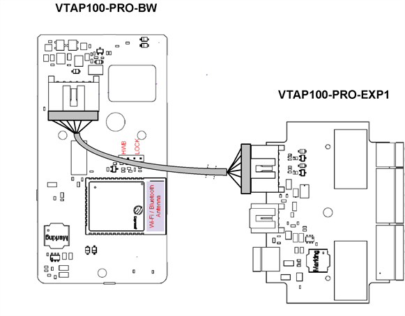
Connecting VTAP100-PRO-EXP1 expansion to the VTAP100-PRO-BW daughter board
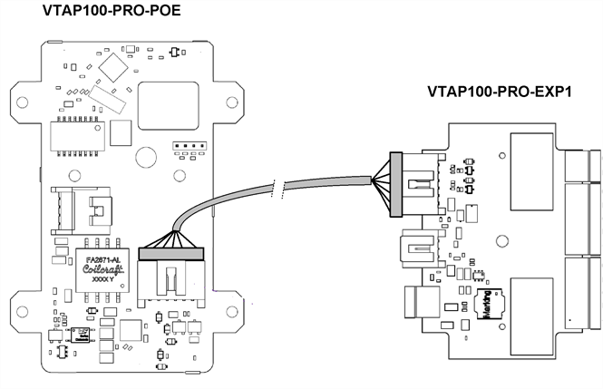
Connecting VTAP100-PRO-EXP1 expansion to the VTAP100-PRO-POE daughter board
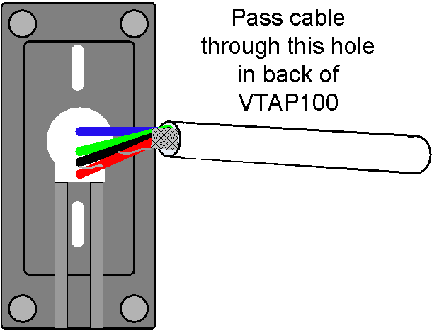
The cable can be routed out through the hole in the back of the VTAP case, and pressed into a guide channel when the product is reassembled. To do this you may need to break or remove a sticker on the rear of the case.
Other lengths of cable are available on request. The maximum length of cable between the VTAP reader and the I/O expansion board is 3m.
If you plan to fix the case to a surface, we recommend that you screw the back of the VTAP reader case to that surface before connecting the EXP cable.
The VTAP PRO I/O expansion board is only suitable for indoor use.
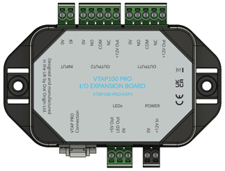
The VTAP100‑PRO‑EXP1 supports I/O options which are labelled as follows:
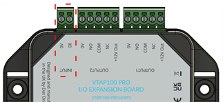
A switch, such as a Request to Exit button, can be connected across the DI and 0V signal INPUT connections.
The INPUT connection is on the 2‑way 3.5mm pitch connector highlighted in the diagram.
The circuit can detect a change of state between input voltage of <1V (input low) and input voltage of >4V (input high). And this input change can trigger a custom script, to perform tasks such as a beep, an LED sequence, or trigger an output.
In Local mode, this input can be monitored by custom software or a script, which will trigger defined operations or perform tasks such as running an LED sequence, buzzer or relay output.
CAUTION: Ensure that there is always a common ground between the VTAP100‑PRO‑EXP1 (via 0V pin on the INPUT connector) and the connected equipment.
, max 5A @ 50V AC
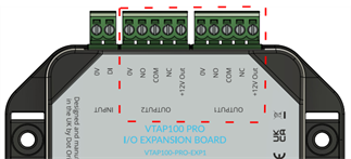
Two OUTPUT relays can be used to switch loads up to 5A @ 50V AC. Normally open (NO), Common (COM) and normally closed (NC) contacts are available, and the outputs can be set to: ON, OFF, timed ON/OFF, or delay ON/OFF. These options support a wide range of scenarios.
Both output connectors provide +12V and up to 1A to power the equipment connected. If the connected equipment requires a higher current, the power must be supplied by using a different wiring scheme.
OUTPUT1 and OUTPUT2 connection is via the two 5‑way 3.5mm pitch connectors highlighted in the diagram.
For a VTAP PRO reader in Cloud mode, a script could trigger either of these output relays, on any of the following events:
-
VTAP reader successful read of an NFC Wallet pass, supported card/tag, or barcode/QR code.
-
VTAP reader failed read (NFCReportReadError) for an NFC Wallet pass or NFC Forum type 4 card/tag.
-
Change in state of the VTAP I/O expansion digital input.
-
Control JSON from a third‑party cloud, with which the VTAP PRO reader is linked through VTAP Cloud.
In Local mode, the VTAP command interface can also be used to drive the relays (OUTPUT1 and OUTPUT2) using free software such as TeraTerm or PuTTY, or your own custom software or script.
Note: Barcode/QR code reading requires a scanner connected to the VTAP PRO reader, either over Bluetooth (VTAP100‑PRO‑BW only) or RS‑232 serial.
VTAP PRO readers can drive external serial LEDs using the VTAP100‑PRO‑EXP1 expansion board. The serial LEDs can be configured to show a default colour or sequence. Alternatively, they could change colour, flash or run an animation in response to events. Those events could be a successful pass or card/tag read, VTAP reader start-up or certain error conditions.
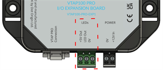
The serial LEDs connection is on the 3‑way 3.5mm connector highlighted in the diagram.
If you are using VTAP PRO readers in Cloud mode, please contact vtap‑support@dotorigin.com to define an LED sequence and triggering event in VTAP Cloud.
In Local mode, the VTAP command interface can be used to drive serial LEDs from a free terminal emulator such as TeraTerm or PuTTY, or your own custom software or script. (Refer to VTAP Application Note on External LED control with VTAP50 for example LED control sequences).
External LED output can be used in VTAP reader applications which require LED feedback, such as:
-
Kiosks;
-
Turnstiles
-
Arcade gaming machines (VTAP PRO readers with a VTAP PRO I/O expansion board replacing the coin mechanism)
Depending on the application, a serial LED matrix, a serial LED strip or combination of the two could be used.
The LEDs output can be configured to drive up to 255 serial LEDs. It uses the Neopixel protocol for driving serial LEDs.
The VTAP100-PRO-EXP1 will supply +5V and up to 1.5A to power an LED strip or matrix. The power drawn by your chosen LEDs (and the way you intend to use them) can restrict the number of serial LEDs that can be supported. The number of LEDs will be most restricted when each RGB LED is being run at full power (white) continuously. If your use only requires red, blue or green, or if a pattern on a matrix will only use a subset of LEDs, then a larger number of LEDs can be supported.
Serial LEDs are typically specified in terms of the current drawn by a single red, green or blue LED. Common LED current specifications are 5mA, 12mA and 20mA. Test results for the number of LEDs of each type that can be powered are given in the following table:
|
Max current per single red, green or blue LED |
5mA |
12mA |
20mA |
|
Voltage |
5V |
5V |
5V |
| Single LED max current drawn at full RGB brightness (white) |
15mA |
36mA |
60mA |
| Max number of LEDs that can be powered at full RGB brightness (white) - 100% duty |
73 |
30 |
18 |
| Max number of single colour (red, green or blue) LEDs that can be powered at full brightness - 100% duty |
220 |
91 |
55 |
| Text on black background - assumed 30% duty |
243 |
100 |
60 |
Any theoretical maximum number of LEDs, using lower power LEDs on a lighter duty cycle, would still be restricted by the 255 maximum number of LEDs that can be configured.
CAUTION: Ensure that there is always a common ground between the VTAP100‑PRO‑EXP1 (via 0V pin on the LEDs connector) and the connected equipment.
The VTAP100‑PRO‑EXP1 is rated at 9 - 15V DC (typ 600mW) for power over the 2‑pin input labelled POWER.
