Connect external LEDs
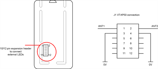
To connect external LEDs with the VTAP50, the 10/12 pin expansion header (not fitted as standard) needs to be soldered in place. Connect your external LED to the expansion header:
Expansion header to connect external LEDs
|
Pin |
Function |
|---|---|
|
1 |
Remote antenna |
|
2 |
Remote antenna |
|
3 |
GND |
|
4 |
GND |
|
5 |
+3V3 (out) |
|
6 |
+5V (in/out) |
|
7 |
LED (red) / LED serial 5V logic |
|
8 |
LED (green) |
|
9 |
LED serial 3V3 logic |
|
10 |
LED (blue) |
|
11 |
Rx (serial comms 3V3) |
|
12 |
Tx (serial comms 3V3) |
For external RGB LEDs: Pins 7, 8, 10 are used, pin 6 for 5V output and either pin 3 or 4 for ground. The VTAP50 supports both common anode and common cathode LEDs, configurable in config.txt. See LED configuration in Config.txt for further details.
For external Serial LEDs: VTAP50 supports 5V and 3V3 logic on different pins. Use pin 7 for 5V logic or pin 9 for 3V3 logic output, pin 6 for 5V output and either pin 3 or 4 for ground.
The external LED outputs are buffered 5V, without any current limiting resistors. You should attach an external LED board or module that includes built-in current limiting resistors. External LEDs should be decoupled, if the LEDs are rated at 5V, and 10μF bulk capacitance per LED along the LED path should be used.
The maximum current that can be drawn through the VTAP50 for external LEDs is 350mA. If your application requires additional current, you should connect an external power source for the LEDs and use only the RGB pins (for RGB LEDs) or logic pins (for serial LEDs) from the VTAP reader, together with ground.
It is recommended you have a common ground between the VTAP reader and the external LED(s). If the LED circuit uses much higher voltages, adequate protection will be needed on the LED circuit, to avoid damage on either side. You could use an opto-isolator on the LED logic output (5V/3V3), for complete isolation between the VTAP reader and LED circuit.
